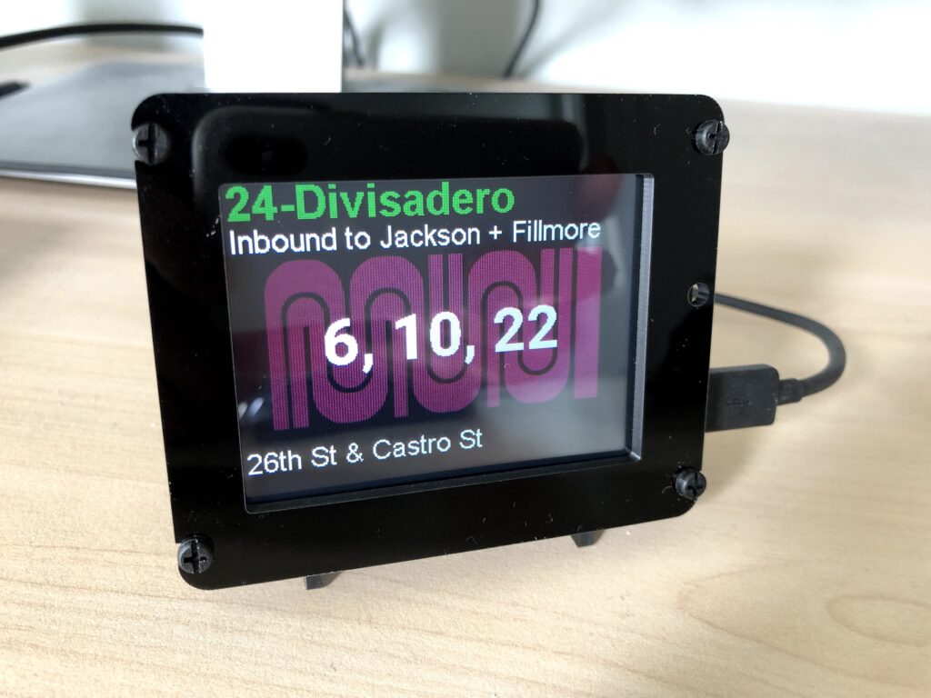
I use an Adafruit PyPortal to check on when buses I regularly take near my house are arriving. Written in CircuitPython, it polls NextBus once per minute and shows upcoming arrival times. It connects to the local WiFi network and uses the built in ambient light sensor to adjust the screen brightness. The code is up on GitLab here: https://gitlab.com/daveparker/muniportal
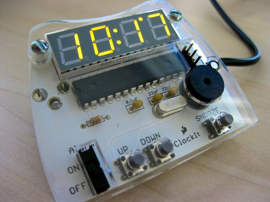
Laser cutters are awesome. They can cut and etch a variety of materials including wood, acrylic, and leather. Laser cutters are one of the favorite tools of makers, artists and engineers alike. I used a laser cutter at TechShop (RIP) to make an acrylic cover for the SparkFun clockit kit. I used 1/3″ clear acrylic to sandwich the circuit board. The cutout design is based off the original PCB design done in Eagle CAD. I replaced the original push-button switches with switches that extended up through the cover (about 1/4 inch). The design file (done in Corel Draw as that is the preferred file format used to drive the Epilog laser cutter) can be found here: Clock-v12_brd_laser.zip.
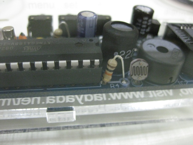
The Ice Tube Clock is a vacuum fluorescent display clock kit from Adafruit industries. I recently put one together and have been enjoying its calming blue glow. Unfortunately at night the calm blue glow is a little on the bright side. While there is a menu option to adjust the brightness it would be better if the clock dimmed automatically. Fortunately, the clock came with a few unused pins on the microcontroller and a space on the circuit board to add a sensor.
I added a resistor and a photocell to act as an automatic dimmer. The microcontroller provides power from one of its pins (which is turned off if the clock is running on battery backup) and senses the voltage across the photoresistor using its analog to digital converter. I added a menu option to turn the dimmer on and off. Its operation is pretty simple. If the room is pretty dark, the display is at minimum brightness. If the room is light, the display is at the brightness set by the user. For extra credit I could add some sort of sensitivity option to the menu but I figured I would start simple and see how well it works. A modified firmware to enable the dimmer control (based off of Adafruit’s Sept 30th firmware) is available there.
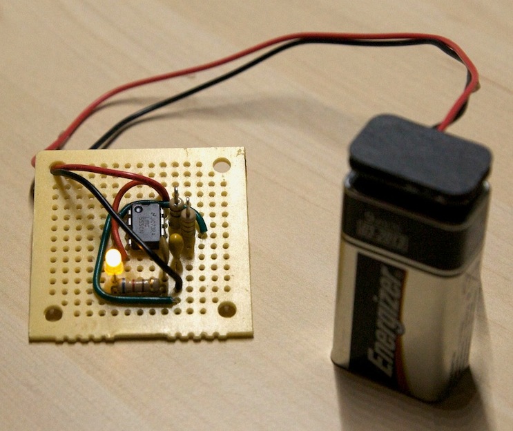
I recently took the electronics safety and basic usage (SBU) class at TechShop so I could make use of the soldering equipment. After making some paperclip men we built a simple blinky using a 555 timer, an assortment of resistors and capacitors, and an LED.
The 555 is a basic building block of many digital circuits. According to wikipedia (555_timer_ic), over a billion were manufactured in 2003 alone. The timer can be used to implement basic logic functions like an inverter or a flip-flop. It can also be used to blink an LED or drive a speaker.
Its operation as an LED blinker is pretty straight forward. The 555 monitors the voltage across a capacitor as it charges and discharges. When the voltage across the capacitor reaches 2/3 the power supply voltage, the 555 flips its output state and also discharges the capacitor. When the capacitor’s voltage drops to 1/3 the power supply voltage, the output is flipped again and the capacitor starts charging. The values of the capacitor and some current limiting resistors (to slow down the charging and discharging) control how fast the 555 changes state and blinks the LED. “The Electronics Club” has a nice write up of 555/556 timer circuits.
One drawback of the 555 is that it isn’t very power efficient. It’s constantly charging and discharging the capacitor and all that energy is thrown away. My blinky ran for about 12 days off of a 9V battery. These days a cheap 8-pin micro-controller (like the ATTiny13A) could perform the same function, with only one resistor to limit the current through the LED (and if you used pulse-width modulation you wouldn’t even need that resistor) for a much longer time. You could also control 5 LEDs with the microcontroller like the Tiny Cylon Kit. Still the 555 has been a workhorse component since it came out in 1971 and many blinking things wouldn’t exist without it….and that would be sad. 🙁
Incidentally, the battery clip in the picture was made from an old 9V battery. I soldered a couple wires to the connections (remember, they are backwards on the clip, the big one is positive) then I used a hot glue gun to stick the bottom of the dead battery to cover up the solder connections.