From the “Pointless but why not?” department comes a tweaked firmware for the ClockIt clock by SparkFun that adds a plain text mode (see video). The new firmware adds a hidden mode to show the time in English using an alphabet created for 7-segment displays. To change modes, press and hold DOWN then press and hold SNOOZE for two seconds (do the same to change back). The other change from the default firmware is that the display will dim between 8PM and 7AM. The modified code is here: clockit-text.zip.
Month: August 2009
Blinkin’ LED with an ATTiny13A

The Arduino development platform makes it easy to get started using microcontrollers to do all sorts of things. The libraries make it easy to use an LCD display, interface with a Nunchuck for the Nintendo Wii, and even fetch data from the web. While this is all well and good I wanted to get a better idea of what the Arduino library code was actually doing behind the scenes.
I decided to forgo the Arduino library and write some code using avr-libc directly. Instead of programming an ATMega168 or ATMega328p, that are standard uC with Arduino boards, I decided to start simple, with an ATTiny13A. This microcontroller is a small 8-pin IC with 1KB of flash memory (for storing programs), 64 bytes of RAM, and 32 8-bit registers. This chip also has a 10 bit analog to digital converter (ADC) for reading voltages and a timer/counter capable of driving two IO pins with pulse-width modulation (PWM).
The “Hello World” equivalent program in the realm of microcontrollers is a program to blink an LED on and off. I thought I would write a jazzed-up version that smoothly transitioned between on and off using PWM. I’d also use the ADC to read in the voltage from a variable resistor to control the speed of the flashing.
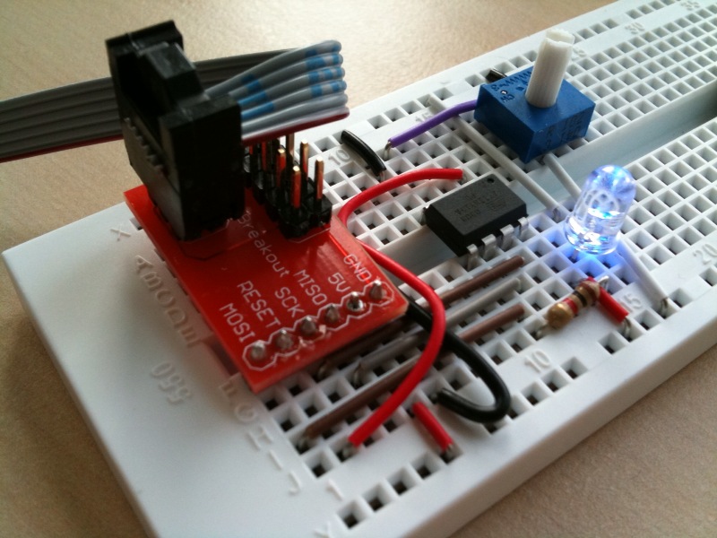
The circuit is pretty straightforward (see the picture). An LED (blue of course!) is attached via a 1K current-limiting resistor to pin 5. The center pin of a 10K pot is connected to pin 3 (the ‘ends’ of the pot go to Vcc and GND). The other wires are used for programming and are connected according to the pinout diagram on the ATTiny13A’s datasheet. The red AVR adapter board from SparkFun makes it easy to plug the programming cable into a breadboard. The programmer I use is the inexpensive and easy to use USBTinyISP from AdaFruit Industries. The programmer provides 5V to the circuit via USB.
I found a few great tutorials that helped me understand how to use the ADC and PWM functions of the microcontroller. These tutorials were written for different Atmel parts, but as the different parts operate similarly I was able to figure out the differences by referring to the datasheet.
Newbie’s Guide to AVR PWM (Incomplete)
Using AVR PWM Modes (PDF requires registration to download).
Newbie’s Guide to the AVR ADC
Here is the blinky light code. I put in some lengthy comments to explain what is going on.
