From the “Pointless but why not?” department comes a tweaked firmware for the ClockIt clock by SparkFun that adds a plain text mode (see video). The new firmware adds a hidden mode to show the time in English using an alphabet created for 7-segment displays. To change modes, press and hold DOWN then press and hold SNOOZE for two seconds (do the same to change back). The other change from the default firmware is that the display will dim between 8PM and 7AM. The modified code is here: clockit-text.zip.
Category: Uncategorized
Blinkin’ LED with an ATTiny13A

The Arduino development platform makes it easy to get started using microcontrollers to do all sorts of things. The libraries make it easy to use an LCD display, interface with a Nunchuck for the Nintendo Wii, and even fetch data from the web. While this is all well and good I wanted to get a better idea of what the Arduino library code was actually doing behind the scenes.
I decided to forgo the Arduino library and write some code using avr-libc directly. Instead of programming an ATMega168 or ATMega328p, that are standard uC with Arduino boards, I decided to start simple, with an ATTiny13A. This microcontroller is a small 8-pin IC with 1KB of flash memory (for storing programs), 64 bytes of RAM, and 32 8-bit registers. This chip also has a 10 bit analog to digital converter (ADC) for reading voltages and a timer/counter capable of driving two IO pins with pulse-width modulation (PWM).
The “Hello World” equivalent program in the realm of microcontrollers is a program to blink an LED on and off. I thought I would write a jazzed-up version that smoothly transitioned between on and off using PWM. I’d also use the ADC to read in the voltage from a variable resistor to control the speed of the flashing.
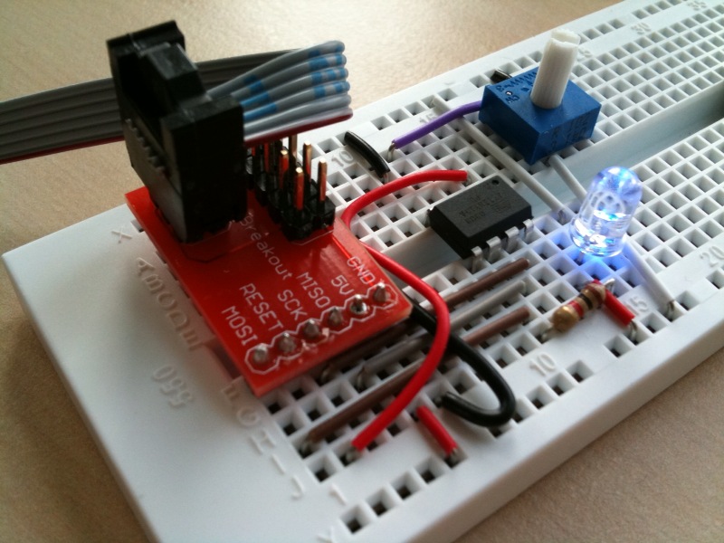
The circuit is pretty straightforward (see the picture). An LED (blue of course!) is attached via a 1K current-limiting resistor to pin 5. The center pin of a 10K pot is connected to pin 3 (the ‘ends’ of the pot go to Vcc and GND). The other wires are used for programming and are connected according to the pinout diagram on the ATTiny13A’s datasheet. The red AVR adapter board from SparkFun makes it easy to plug the programming cable into a breadboard. The programmer I use is the inexpensive and easy to use USBTinyISP from AdaFruit Industries. The programmer provides 5V to the circuit via USB.
I found a few great tutorials that helped me understand how to use the ADC and PWM functions of the microcontroller. These tutorials were written for different Atmel parts, but as the different parts operate similarly I was able to figure out the differences by referring to the datasheet.
Newbie’s Guide to AVR PWM (Incomplete)
Using AVR PWM Modes (PDF requires registration to download).
Newbie’s Guide to the AVR ADC
Here is the blinky light code. I put in some lengthy comments to explain what is going on.
Ambient Nextmuni Monitor Prototype

I take the bus at least once a week to get around San Francisco. There is a local bus stop a block from the house that gets me to the Castro muni station where I can then go downtown on the inbound K, L, or M lines. I use www.nextmuni.com to find out when the next bus will be at my local stop. However, as I’m running around in the morning getting ready, I tend to loose track of exactly when I need to get my butt out of the front door.
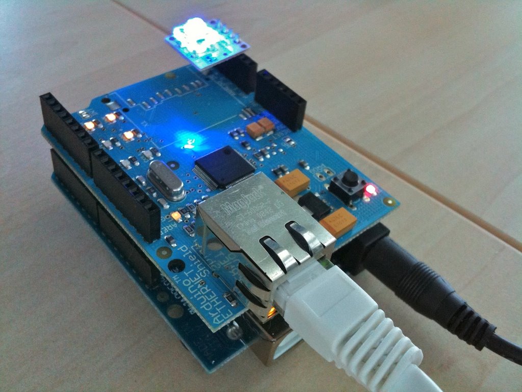
I figured all I really needed was an ambient device that I could glance at so I’d know when to leave. As a first step I built a prototype using an Arduino microcontroller board, an Arduino Ethernet shield, and a BlinkM smart tri-color LED.
The LED flashes green when it’s the perfect time to leave (which for me is about 5-6 minutes until the bus arrives). The LED flashes orange then red as the bus gets closer. If the bus is more then 15 minutes away the LED is solid red. It then turns solid yellow then solid green before flashing green as the bus approaches. The LED turns blue when it’s updating.
The Arduino sketch for the monitor is available here. The monitor’s IP address and bus stop information are currently hard coded. For a future version I’d like to add a webserver so settings like the bus stop and update frequency could be altered and stored in EEPROM without needing to recompile the code. Ultimately I also want to build a dedicated version that has just the needed components. Perhaps I could fit it inside a small toy bus?
ClockIt – 7-segment strings
My obsession with the ClockIt clock from SparkFun continues. I like how simple it is. It’s a microcontroller directly wired to a 4 digit LED display, a piezo speaker, and a few switches. I’m finding it a good project for getting used to working with gcc-avr directly without the training wheels offered by the arduino platform. In the video you can see that I’ve written some code to display alpha-numeric strings. I followed suggestions on Wikipedia on how to represent some of the more complex characters. It’s a little weird, but you get used to it. My end-goal for this project is to have the clock spell out the time in English. Pointless, but educational.
I’m thinking I could also have it tell me what electricity rate we’re currently on as part of PG&E’s net metering scheme (peak, partial peak, or off peak). In order to do this properly I’d have to support the date as there are different daily schedules for the summer and the other seasons. The same functionality might work better as an ambient orb like device. It could be red for peak, yellow for partial peak, and green for off peak. I’ll have to think about which I’d like to do.
Some other project ideas I have for the clock are a kitchen timer (obvious I suppose), and a thermometer using a 1-wire digital thermometer IC connected to the one free I/O pin on the microcontroller. I already have some code written for the kitchen timer idea although it needs some clean-up before I post it.
Incidentally, SparkFun recently published the PCB layout files for ClockIt under a creative commons share-alike license making it one of their first open hardware projects. The layout files are for the Eagle layout software by CadSoft. There is a free version of Eagle for non-commercial use that allows you to create 2-sided PCBs up to 4×3.2 inches in size. SparkFun offers a PCB fab service to implement your design for $2.50 per square inch.
Peggyboard – A message board for Peggy2

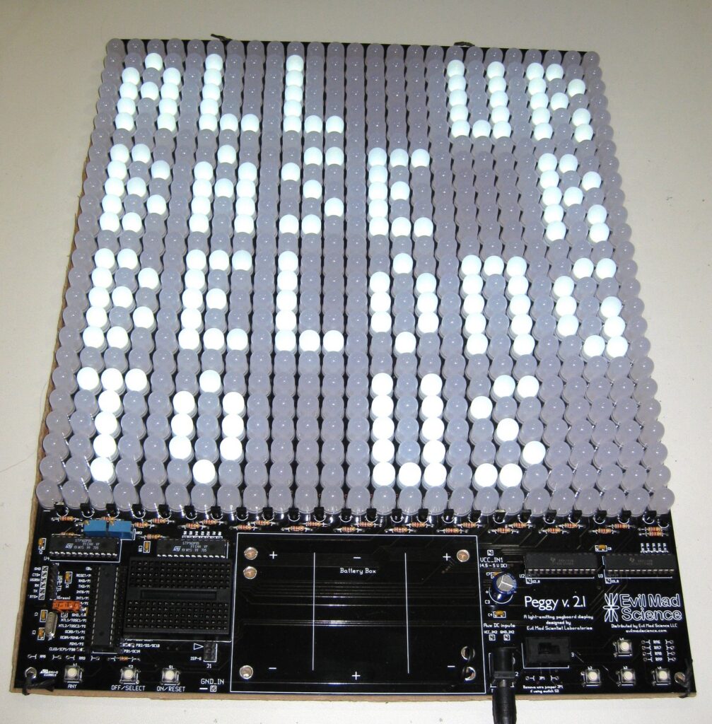
Peggy2 is an electronic peg board with a matrix of 25×25 LEDs. Peggy2 was designed by Evil Mad Scientist Laboratories and kits are available on their store site. I built a peggy2 earlier this year and have been tinkering with it.
Peggy2 is Arduino compatible as it’s run by an ATMega168 (or 328p) microcontroller. One of the first projects I worked on was a simple message board program called peggyboard. This program lets you write and save a message using the navigation buttons. The characters are 3×5 pixels each allowing for 6×4 characters on the board. The message is stored in EEPROM so it can be re-displayed when you turn the peggy back on.
Here is the Arduino sketch for Peggyboard. You also need the Peggy2 library installed in order to compile the sketch.
